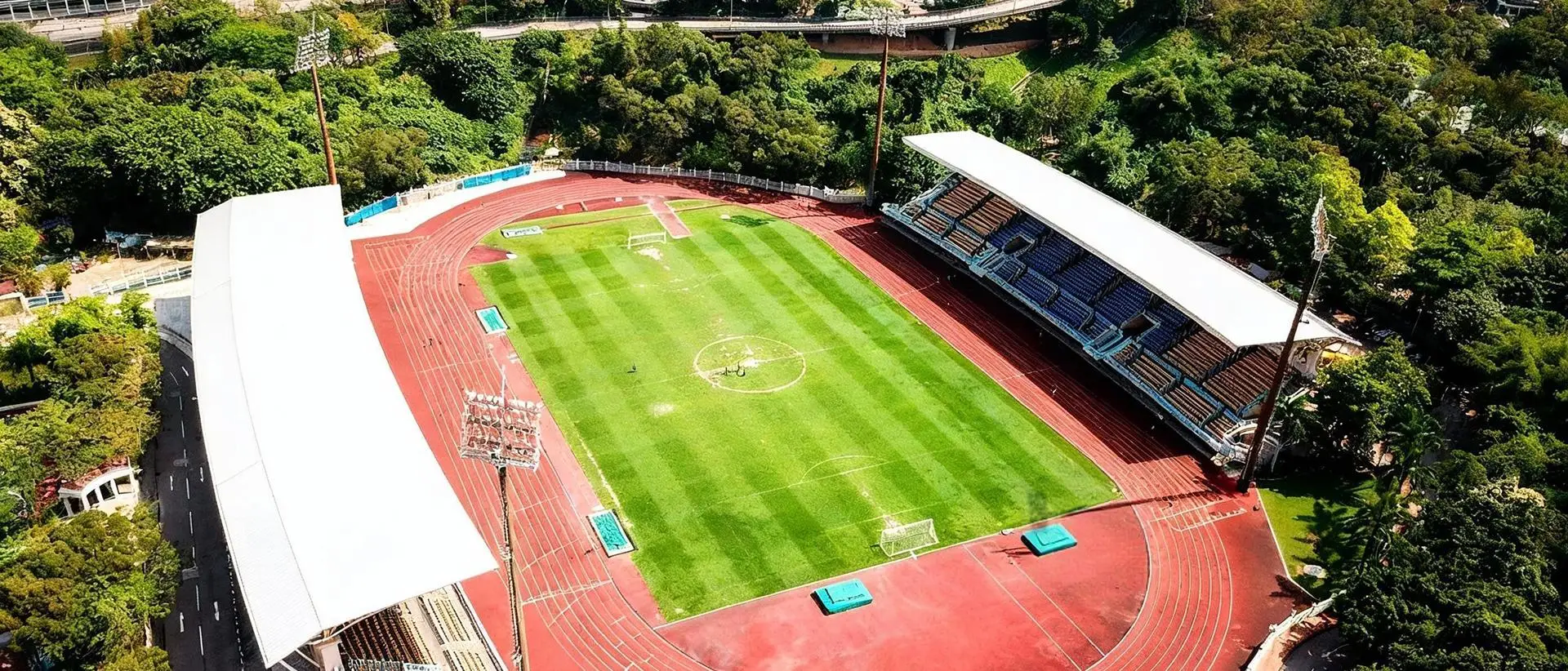
LED sports lighting is now the preferred solution for many outdoor stadiums because it combines…
Street Lighting Design Guide: Layout, Spacing and Optics
A successful street lighting design does more than make a road look bright. It must help drivers detect vehicles, pedestrians and obstacles early while controlling glare, energy use, light spill and maintenance costs.
An effective design is based on the road classification, required lighting level, optical distribution, pole height, pole spacing and environmental conditions. Simply choosing a high-wattage LED street light does not guarantee good visibility or uniform illumination.
This guide explains the main steps involved in LED street lighting design and provides practical starting points for urban roads, highways, sidewalks, parking areas and public spaces. Final values should always be verified through a project-specific photometric simulation and the applicable local standard.
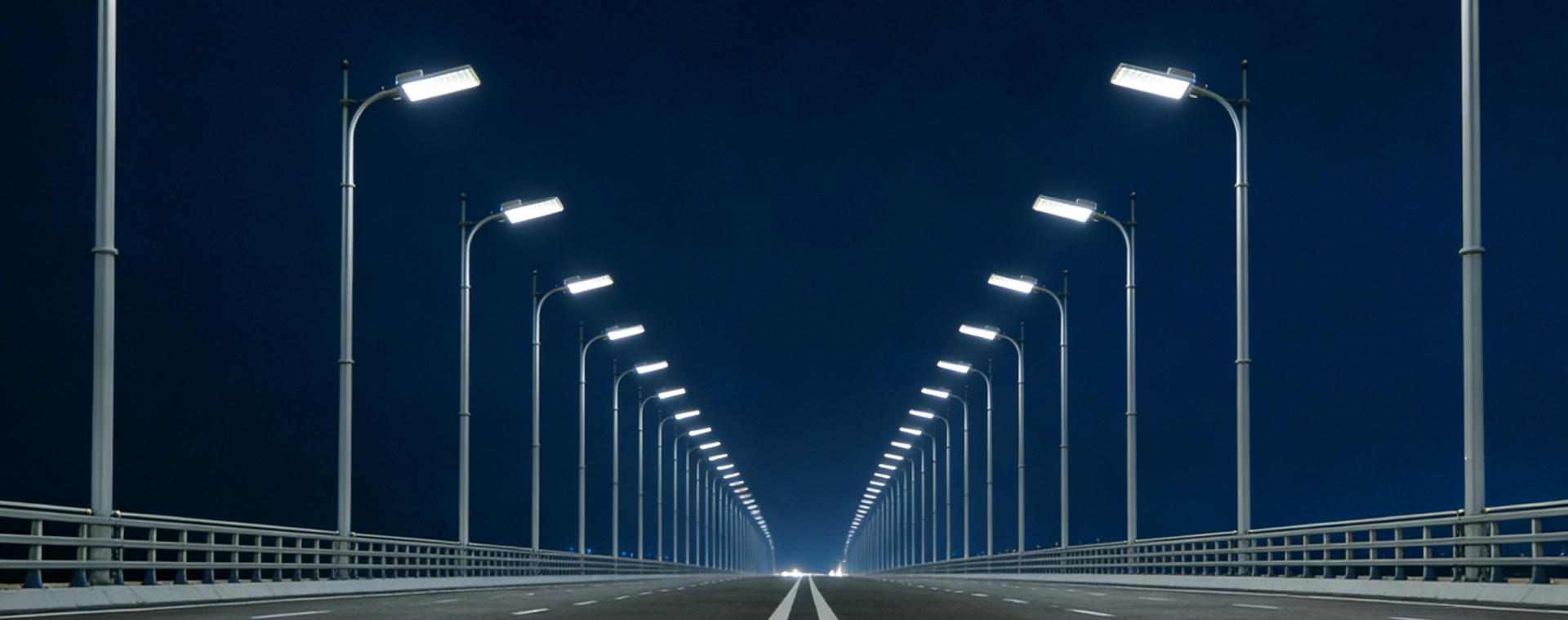
What Makes a Good Street Lighting Design?
Street lighting quality cannot be judged by wattage or total lumens alone. A powerful luminaire may still produce poor results if the beam distribution is unsuitable for the road width, pole position or mounting height.
A well-engineered street lighting design should balance the following factors:
- Average luminance or illuminance
- Overall and longitudinal uniformity
- Glare control
- Visibility of pedestrians and roadside obstacles
- Energy efficiency
- Light spill and upward-light control
- Equipment reliability
- Installation and maintenance costs
- Smart control and future upgrade capability
The objective is to provide sufficient and uniform illumination without creating excessive brightness, dark areas or uncomfortable glare.
The CIE 115:2010 road-lighting publication classifies road lighting according to motorized traffic, conflict areas and pedestrian spaces. Local regulations and standards such as EN 13201 or ANSI/IES RP-8 may impose additional project requirements.
Step 1: Classify the Road and Its Users
The first step is to understand how the road or public area is used at night.
Collect the following project information:
- Road type and number of lanes
- Road width and median configuration
- Vehicle speed
- Nighttime traffic volume
- Pedestrian and cyclist activity
- Intersections and pedestrian crossings
- Curves, slopes and conflict zones
- Road-surface condition
- Nearby residential properties
- Existing pole positions
- Utility and maintenance restrictions
High-speed roads normally require stricter glare control and luminance-based evaluation. Residential roads, sidewalks, parks and pedestrian spaces are more commonly assessed through horizontal and vertical illuminance.
Intersections, roundabouts and pedestrian crossings should be treated as conflict areas. They may require different lighting levels, pole positions or optical distributions from the adjoining road.
Step 2: Set the Lighting Performance Targets
After determining the road class, establish measurable lighting targets before selecting a luminaire.
Depending on the project and applicable standard, the main parameters may include:
Average luminance
Average luminance measures how bright the road surface appears to a driver. It is normally expressed in candela per square metre, or cd/m².
Average illuminance
Illuminance measures the amount of light reaching a surface and is expressed in lux. It is commonly used for sidewalks, pedestrian areas, parking lots and lower-speed roads.
Overall uniformity
Overall uniformity compares the minimum light level with the average light level. Poor uniformity creates bright and dark patches that make it more difficult for drivers to identify objects.
Longitudinal uniformity
Longitudinal uniformity evaluates brightness consistency along the direction of travel. Inadequate longitudinal uniformity can create a repetitive bright-and-dark “zebra effect.”
Threshold increment
Threshold increment, or TI, is used to evaluate disability glare. Excessive glare temporarily reduces the driver’s ability to identify obstacles and other road users.
Surround ratio
Surround ratio evaluates illumination immediately outside the carriageway. Adequate surrounding light helps drivers see pedestrians, animals and objects near the roadside.
Do not choose a product only from its wattage or lumen output. A photometric calculation must demonstrate that the complete installation meets the required values.
Step 3: Choose the Correct Light Distribution
Optical distribution determines where a street light directs its output. Selecting the correct lens can improve uniformity, increase usable pole spacing and reduce unwanted glare.
Common roadway distributions include:
Type II
Type II distributions are generally suitable for narrower roads, sidewalks, cycle paths and roadside installations where the road width is approximately equal to or slightly greater than the pole height.
Type III
Type III distributions provide greater forward and lateral coverage. They are commonly used for urban roads, parking areas and medium-width carriageways.
Type IV
Type IV optics project light further forward and are useful when luminaires are positioned along one side of a wider road or open area.
Type V
Type V distributions provide a more symmetrical pattern. They are typically used in squares, open parking areas and centrally mounted applications.
For example, the G7 Series LED street light offers multiple optical distributions for different road and lane arrangements.
The G10 Series flip-top LED street light uses a Type II-M roadway distribution and supports horizontal or vertical mounting.
Step 4: Determine Pole Height, Spacing and Layout
Pole height and spacing must be evaluated together. A higher mounting position usually improves coverage and uniformity, but it may also require greater lumen output.
Excessive spacing can create dark areas even when the calculated average illuminance appears acceptable.
The following values can be used as preliminary planning ranges:
| Road condition | Typical arrangement | Starting pole height | Starting spacing |
|---|---|---|---|
| One or two narrow lanes | Single-sided | 6–8 m | 20–30 m |
| Two-lane urban road | Staggered | 8–10 m | 25–35 m |
| Four lanes with median | Opposite or central dual-arm | 10–12 m | 30–40 m |
| Road with active sidewalks | Opposite or staggered | 8–10 m | 25–30 m |
| Wide arterial road | Opposite or central dual-arm | 12–15 m | 35–45 m |
As an initial rule of thumb, street light spacing is often approximately three to four times the mounting height.
For example, a pole height of 10 metres may provide an initial spacing range of approximately 30–40 metres. However, this is only a starting point. The actual result depends on:
- Road width
- Luminaire output
- Beam distribution
- Pole setback
- Overhang
- Mounting angle
- Road reflectance
- Required uniformity
- Presence of sidewalks and cycle lanes
Curves, intersections, pedestrian crossings and changes in road width normally require shorter spacing or additional luminaires.
Common Street Light Pole Arrangements
Single-sided arrangement
All poles are installed along one side of the road.
This layout is suitable for narrow roads where the carriageway width is not significantly greater than the mounting height. It offers lower installation costs but may produce insufficient uniformity on wider roads.
Staggered arrangement
Poles are installed alternately on both sides of the road.
A staggered arrangement can improve coverage on medium-width roads while avoiding the cost of directly opposite pole pairs. Careful photometric verification is needed to prevent alternating bright and dark areas.
Opposite arrangement
Poles are installed directly opposite each other on both sides of the road.
This layout provides strong symmetry and uniformity for wider roads, main streets and roads with sidewalks on both sides.
Central dual-arm arrangement
Poles are installed in the central median with two luminaires illuminating opposite carriageways.
This arrangement can reduce the number of pole foundations but requires a sufficiently wide and accessible median.
Step 5: Select Output, Efficacy and Color Temperature
Luminaire wattage should be the result of the lighting calculation—not the first design decision.
Compare LED street lights using:
- Delivered lumen output
- System efficacy
- Photometric distribution
- Glare performance
- Maintained lumen output
- Driver efficiency
- Power factor
- Total harmonic distortion
- Temperature performance
- Control compatibility
High-efficacy luminaires can reduce connected power, but efficiency should not come at the expense of glare control or optical performance.
The G9 Series 300W LED street light, for example, delivers efficacy up to 190 lm/W with Type II-M distribution and optional intelligent controls.
Choosing the color temperature
Color temperature should match the environment and local regulations.
- 2200K–3000K: Suitable for residential areas, parks, environmentally sensitive locations and projects requiring reduced blue-light content.
- 3000K–4000K: A common choice for urban roads, mixed-use areas and commercial districts.
- 5000K and above: Sometimes specified for industrial roads and high-activity areas, but environmental impact, glare and community preference should be reviewed carefully.
CRI 70 is common for general roadway lighting. Pedestrian, commercial and security-sensitive areas may benefit from CRI 80 or higher.
Step 6: Check Outdoor Durability
Street luminaires operate continuously in rain, dust, heat, vibration and electrical disturbances. Outdoor durability should be included in the specification.
| Item | Recommended consideration |
|---|---|
| Ingress protection | IP66 is commonly specified for exposed street lights |
| Impact resistance | IK08–IK10 depending on location and vandalism risk |
| Surge protection | Select according to the electrical grid and lightning exposure |
| Housing | Corrosion-resistant die-cast aluminum |
| Fasteners | Corrosion-resistant hardware and anti-drop components |
| Driver | Replaceable, protected and accessible for maintenance |
| Operating temperature | Must cover the actual project environment |
| Photometric data | Current IES or LDT file for the exact configuration |
| Warranty | Confirm coverage for the luminaire, driver and controls |
Coastal, tropical and heavy-industrial environments may require enhanced powder coating, stainless-steel hardware and additional salt-spray testing.
Surge protection is especially important for road lighting because poles and power cables may be exposed to lightning-induced voltage surges. Depending on the installation environment, 10kV or 20kV surge protection may be appropriate.
Step 7: Plan Smart Street Lighting Controls
Smart controls can reduce energy consumption and simplify maintenance without compromising road safety.
Available control methods may include:
- Photocell switching
- Scheduled dimming
- 0–10V dimming
- DALI control
- Zigbee wireless control
- LoRa communication
- Central management systems
- Remote fault alarms
- Energy monitoring
NEMA and Zhaga sockets allow sensors and controllers to be installed or upgraded without replacing the entire luminaire.
A typical smart street lighting schedule may use:
- Full output during peak traffic periods
- Reduced output during late-night low-traffic periods
- Automatic return to full output when required
- Remote monitoring of power consumption and equipment faults
Any dimming schedule must continue to meet the minimum lighting class required for the road.
Step 8: Apply a Suitable Maintenance Factor
Street lighting performance decreases over time because of:
- LED lumen depreciation
- Dirt accumulation
- Lens aging
- Driver performance
- Environmental exposure
- Maintenance intervals
A lighting design must therefore use maintained—not only initial—lumen output.
The maintenance factor should reflect the luminaire construction, local pollution level, cleaning schedule and expected LED depreciation. Using an unrealistic maintenance factor may produce a design that passes during installation but fails to meet the target after several years.
Step 9: Verify the Design With Photometric Software
Every street lighting design should be checked using professional calculation software such as DIALux, AGi32 or Relux.
The simulation must use the actual IES or LDT file for the selected:
- Product model
- Wattage
- Optical distribution
- Color temperature
- LED configuration
The model should also include:
- Road dimensions
- Lane positions
- Sidewalks and cycle lanes
- Pole height
- Pole spacing
- Pole setback
- Luminaire overhang
- Mounting angle
- Surface reflection properties
- Maintenance factor
The final report should show:
- Calculation grid
- Luminaire model and quantity
- Wattage and lumen output
- Pole positions
- Average and minimum results
- Overall uniformity
- Longitudinal uniformity
- Glare results
- Surround ratio
- Connected load
- Proposed control schedule
The U.S. Department of Energy provides a useful model specification for LED roadway luminaires for municipalities and organizations preparing procurement documents.
Common Street Lighting Design Mistakes
Choosing wattage before defining the road class
Wattage alone cannot predict road brightness, uniformity or glare. Begin with the visual requirements and road geometry.
Using the same optic for every road
A lens suitable for a narrow residential street may perform poorly on a wide arterial road. Match the optical distribution to the actual layout.
Maximizing spacing only to reduce pole quantity
Increasing spacing may reduce installation costs but can create dark zones, poor uniformity and uncomfortable brightness contrast.
Ignoring sidewalks and roadside areas
A road may meet carriageway requirements while leaving pedestrians poorly illuminated. Include sidewalks, crossings and surrounding areas in the calculation.
Tilting luminaires unnecessarily
Excessive tilt can increase glare, light spill and upward light. Modern roadway optics should normally achieve the required coverage with limited or no upward tilt.
Using generic photometric files
The IES or LDT file must match the exact product, wattage and lens supplied. A generic file can produce inaccurate results.
Forgetting the maintenance factor
Calculating only initial performance may cause the installation to fall below the required level as the luminaire ages.
Ignoring maintenance access
Drivers, surge protectors and controllers should be replaceable safely. Tool-free compartments and anti-drop screws can reduce maintenance time.
Street Lighting Design Checklist
Before approving a street lighting proposal, confirm that you have:
- Identified the correct road or pedestrian lighting class
- Defined luminance or illuminance targets
- Defined uniformity and glare requirements
- Selected the appropriate optical distribution
- Verified pole height and spacing
- Included pole setback, overhang and mounting angle
- Calculated sidewalks and roadside areas
- Confirmed IP, IK and surge-protection ratings
- Considered local temperature and corrosion conditions
- Applied a realistic maintenance factor
- Evaluated dimming and smart controls
- Used an exact IES or LDT file
- Completed a project-specific photometric simulation
- Checked the applicable local standard and tender specification
Conclusion
Effective street lighting design begins with the visual task and required lighting class, not with a preferred wattage.
Correct optical distribution, sensible pole geometry, glare control, durable luminaires and verified photometric calculations must work together to create a safe, comfortable and energy-efficient installation.
ROKEE provides LED street lights with multiple wattages, roadway distributions, mounting methods and intelligent control options. Explore the complete LED street light range or contact the ROKEE Lighting team for a project-specific product recommendation and lighting layout.
Related Posts