
CRI and TLCI both describe color performance, but they answer different questions. Learn how to specify LED sports lighting for spectators, players and broadcast cameras.
Trunnion Mount: Types, Selection and Installation
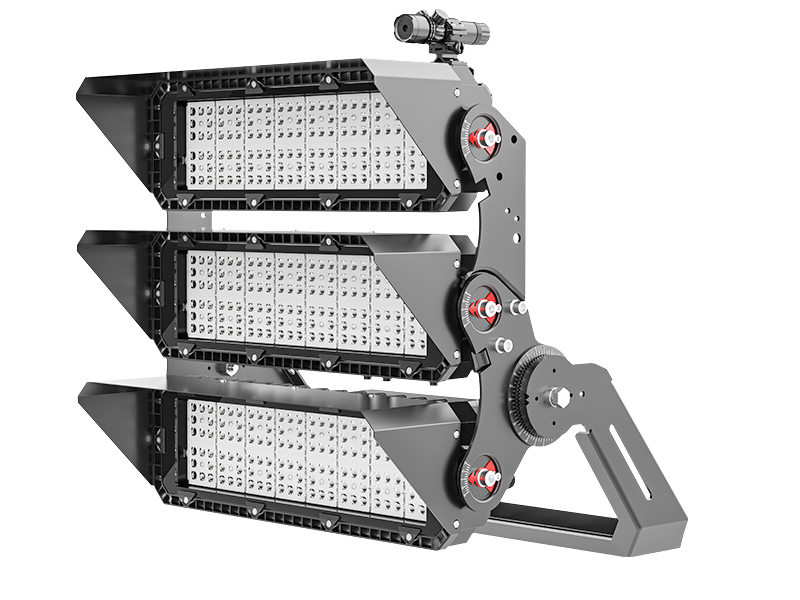
A trunnion mount supports a light fixture between two bracket arms and lets the housing pivot to the required aiming angle. On LED floodlights, the bracket is normally fixed to a wall, beam, crossarm, platform or other prepared surface. The installer rotates the luminaire around its side pivots, checks the aim and locks it in position.
It looks simple, but the bracket is part of the structural and optical design. Its hole pattern must fit the mounting surface, its rated load must suit the luminaire and its adjustment range must reach the calculated aiming point. Ordering “a U-bracket” without those details is a common way to create extra drilling and improvised hardware on site.
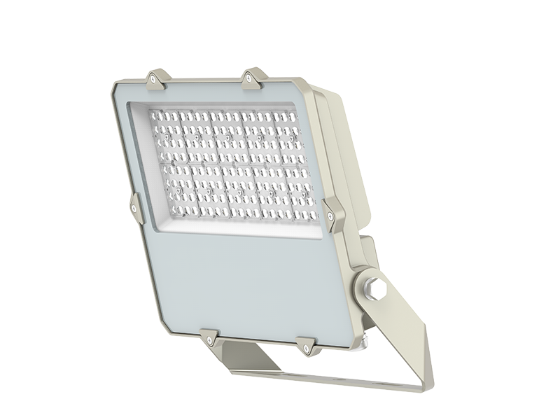
What is a trunnion mount?
In lighting, a trunnion mount is an adjustable bracket with a base and two arms that connect to opposite sides of the luminaire. The pivot points carry the fixture and provide a controlled axis of rotation. Once the light is aimed, the side fasteners are tightened according to the manufacturer’s instructions.
The terms trunnion mount, yoke mount and U-bracket are often used for similar hardware. They are not guaranteed to mean an identical hole pattern, material thickness or adjustment mechanism. Treat the supplier’s dimensional drawing and installation sheet as the definition for the product being purchased.
This mounting style is common on:
- building and façade floodlights;
- yard, apron and loading-area lights;
- sports and high-mast floodlights;
- tunnel and underpass luminaires;
- sign, billboard and architectural projectors;
- marine and industrial floodlights.
How the bracket carries and aims the light
The bracket base transfers the fixture weight and environmental loads into the supporting structure. The two arms resist bending and hold the housing at its pivots. Slots, serrations, angle markings or friction at the side joints allow adjustment, depending on the product.
That arrangement normally provides adjustment in one plane. If the bracket is attached to a horizontal surface, the fixture tilts up or down. If it is fixed to a vertical face, the same physical movement produces a different aiming arc. Horizontal rotation needs to come from the base orientation, an additional adaptor or another mounting system.
Do not assume a bracket can rotate through a full semicircle. Cable bend radius, housing clearance, driver position and the certified mounting orientation can all limit the usable range. A product drawing should show the permitted angles and any prohibited positions.
Trunnion mount versus other floodlight mounts
| Mounting type | Typical attachment | Main advantage | Check before ordering |
|---|---|---|---|
| Trunnion or yoke | Flat surface, beam, crossarm or mounting plate | Stable support and direct tilt adjustment | Base footprint, fastener holes, load rating and aiming range |
| Slip fitter | Round tenon at the top or side of a pole | Convenient pole mounting with rotational adjustment | Tenon outside diameter, insertion depth and angle range |
| Knuckle | Threaded hub or compact junction-box interface | Small footprint for lighter fixtures | Thread size, fixture weight and permitted orientation |
| Direct arm | Dedicated pole or wall adaptor | Clean appearance and controlled fit | Compatibility with the exact pole and luminaire family |
A trunnion mount is usually the practical choice when a floodlight must bolt to steelwork or a solid surface and remain adjustable. A slip fitter is often easier on a standard pole tenon because it can provide both tilt and horizontal rotation. A compact knuckle suits smaller floodlights, but it should not be treated as a substitute for a heavy bracket on a large fixture.
Information needed to specify the bracket
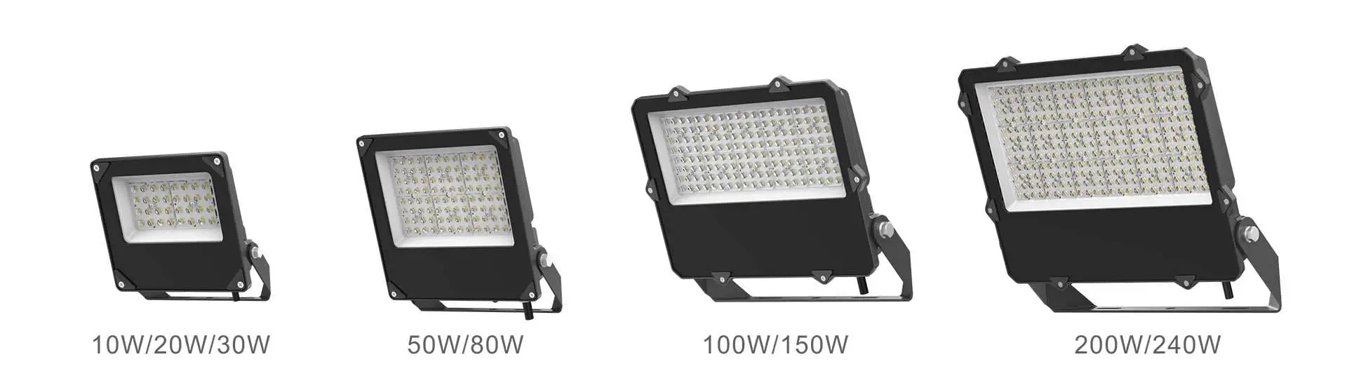
Start with the exact luminaire model, not just its wattage. Two 200 W floodlights can have different weights, centres of gravity and side fixing points. The bracket supplied for one housing may not be safe or physically compatible with the other.
Luminaire weight and centre of gravity
The supporting structure must carry more than the static fixture weight. The bracket also sees leverage from the housing, vibration and wind. A deep or front-heavy luminaire can place a much larger moment on the base than a compact fixture of the same mass.
Mounting surface and hole pattern
Request a dimensioned drill template showing hole diameters, slot lengths, spacing and bracket footprint. Confirm whether the base will sit on concrete, structural steel, a pole crossarm, a wall plate or another adaptor. Thin cladding and decorative sheet metal are not structural mounting surfaces unless specifically reinforced.
Material and corrosion exposure
Bracket material, coating and fasteners need to match the environment. Coastal, chemical and wash-down sites deserve particular attention. Mixing dissimilar metals without suitable isolation can create galvanic corrosion, while damaged coatings around drilled holes can become the first failure point.
Cable entry and junction location
The bracket must leave room for the supply cable, gland, flexible conduit and junction box. The cable should not be pulled tight or crushed as the light moves through its aiming range. A weatherproof luminaire does not make an exposed splice weatherproof; the complete connection method needs the required environmental rating.
Wind loading and projected area
For exposed outdoor work, use the manufacturer’s effective projected area or the required engineering data for the exact housing and aiming position. Tilting a flat floodlight changes the area presented to the wind. The bracket, fasteners, crossarm, pole and foundation form one load path and should be checked together.
Plan the aiming before installation
The bracket does not decide where the light should point. A photometric layout should establish each fixture location, beam distribution, tilt and orientation. Installers then need an aiming schedule that identifies the luminaire, target point and reference angle in a form that can be checked on site.
Aiming only by looking at the bright patch on the ground often produces poor uniformity and unnecessary spill light. Narrow-beam sports and high-mast fixtures are especially sensitive: a small angular error can move the beam centre a long distance at the target plane.
A useful site method is to:
- mark every luminaire and bracket position to match the drawing;
- set a preliminary tilt using a digital inclinometer or the specified aiming tool;
- orient the fixture toward the scheduled target point;
- tighten the adjustment hardware in the stated sequence and to the specified torque;
- record the final setting;
- verify illuminance, uniformity, glare and spill light after dark.
Angle markings cast into a bracket are useful references, but they may not equal the photometric tilt convention used in the lighting calculation. Agree on the zero position before installation begins.
Installation sequence for a trunnion-mounted light
The product instructions and project drawings control the work. A typical sequence is as follows:
- Isolate the supply. Confirm the circuit is de-energized and follow the site’s lockout procedure.
- Inspect the parts. Check the bracket, pivot hardware, cable gland, housing and finish for damage or missing components.
- Verify the structure. Confirm the prepared surface, reinforcement, anchors and clearances match the approved drawing.
- Fix the bracket base. Use the specified fastener type, size, washers, locking method and torque. Hardware is not interchangeable merely because it fits through the slot.
- Attach or position the luminaire. Support the fixture during assembly. Do not let its full weight hang from one loose pivot bolt or from the supply cable.
- Complete the electrical connection. Maintain grounding, conductor ratings, cable seals, drip loops and enclosure ratings required for the location.
- Aim and lock the fixture. Loosen only the hardware identified for adjustment, set the scheduled angle and retighten it as instructed.
- Inspect and test. Check clearances, cable movement, fastener security, operation and control response before the final lighting survey.
Published installation instructions from major manufacturers consistently treat angle adjustment and fastener tightening as product-specific operations. Use the torque and tilt limits for the supplied bracket; values copied from another fixture can damage threads or leave the assembly insecure.
Common mistakes and how to avoid them
Buying a “universal” bracket without drawings
A bracket may fit the luminaire but miss the existing holes in the crossarm. Obtain both the luminaire-side dimensions and the base drill pattern before release for manufacture.
Using the adjustment slot as the only structural fixing
Slots help alignment; they do not remove the need for the specified number of fasteners, washers and bearing area. The approved mounting detail should show how the base is restrained.
Ignoring cable movement
A cable that looks acceptable at zero tilt may tighten around an edge when the floodlight is aimed. Move the fixture through its permitted range before finalizing the cable length and gland position.
Changing the tilt after the photometric approval
Raising the beam to reach farther can increase glare and light beyond the property boundary. Update the model or return to the approved aiming schedule rather than correcting the result by eye.
Drilling the bracket on site
Unapproved holes can weaken the section and break the protective coating. If the base does not fit, use an engineered adaptor plate or obtain the correct bracket.
Trunnion mount selection checklist
- exact luminaire model, weight and centre of gravity;
- bracket material, finish and fastener material;
- fixture-side and base-side dimensional drawings;
- permitted mounting orientation and aiming range;
- effective projected area or required wind-load data;
- supporting surface, crossarm or adaptor details;
- anchor or bolt specification and installation torque;
- cable, gland, conduit and junction-box arrangement;
- photometric aiming schedule and field verification method;
- access for future tightening, cleaning and driver service.
ROKEE’s LED flood light range includes adjustable bracket configurations for outdoor and industrial projects. For sports fields and longer throwing distances, review the LED sports light range. Send the luminaire schedule, mounting detail, aiming angles and environmental conditions so the bracket and optical configuration can be checked together.
Frequently asked questions
Is a trunnion mount the same as a yoke mount?
The terms are often used for the same U-shaped adjustable lighting bracket, but product details vary. Confirm the dimensional drawing, load rating and adjustment mechanism instead of relying on the name alone.
Can a trunnion mount be installed on a wall or ceiling?
Only when the luminaire documentation permits that orientation and the supporting structure is suitable. The available aiming direction, drainage, cable entry and thermal behaviour can change with orientation.
Can any trunnion bracket fit any LED floodlight?
No. Side fixing points, housing width, pivot hardware, weight and centre of gravity differ between products. Use the bracket approved for the exact luminaire or an engineered adaptor.
Does a trunnion bracket provide horizontal rotation?
It normally provides tilt around one axis. Horizontal orientation may require repositioning the base, using a rotating adaptor or choosing a slip-fitter system.
How should a trunnion-mounted floodlight be aimed?
Use the approved photometric aiming schedule, a defined zero position and a suitable measuring tool. Record the final setting, tighten the hardware as instructed and verify the completed lighting after dark.
Technical references
Related Posts