
CRI and TLCI both describe color performance, but they answer different questions. Learn how to specify LED sports lighting for spectators, players and broadcast cameras.
High Bay Light Spacing and Mounting Height Guide
High bay light spacing cannot be selected from mounting height alone. The correct distance between fixtures depends on the luminaire’s actual light distribution, delivered lumens, target maintained illuminance, work-plane height, room surfaces and obstructions. A 12 m warehouse may use 8 m spacing with one optic and 12 m with another, even when both fixtures draw the same wattage.
A spacing table is useful for the first sketch. The final layout should always be checked with the exact IES or LDT file because the calculation has to show minimum light levels, uniformity and glare—not just an average lux figure.
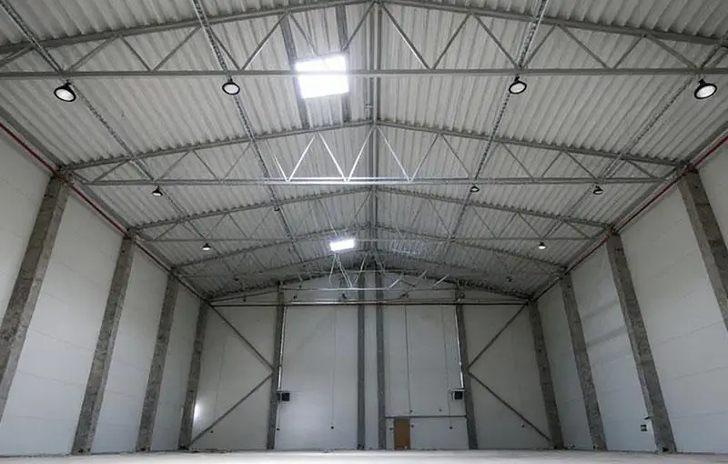
Measure mounting height from the work plane
Lighting calculations use the distance between the luminaire and the surface being evaluated. If a high bay is mounted 10 m above the floor and the relevant work plane is 0.8 m high, the effective mounting height is 9.2 m. For a loading aisle evaluated at floor level, it is the full 10 m.
This distinction matters in factories with raised machines, mezzanines or inspection benches. Using ceiling height as the mounting height can produce a grid that is too wide for the actual task.
A practical high bay light spacing table
The following ranges assume modern LED high bays with appropriate optics and a general industrial target in the region of 200–300 maintained lux. They are preliminary layout ranges, not guaranteed results.
| Fixture height above work plane | Typical delivered lumens | Starting spacing | Common application |
|---|---|---|---|
| 5–6 m | 10,000–18,000 lm | 5–7 m | Low warehouses, workshops, retail stock areas |
| 7–9 m | 18,000–28,000 lm | 7–9 m | General storage and production |
| 10–12 m | 28,000–42,000 lm | 9–12 m | High-rack warehouses and large factories |
| 13–16 m | 40,000–60,000 lm | 11–15 m | Distribution centres, aircraft or heavy-industry bays |
If the task needs 500 lux, if the walls and roof are dark, or if tall racking blocks lateral light, tighten the grid. If the area is open, reflective and used mainly for circulation, a wider grid may work. The range is a way to begin drawing, not a substitute for the calculation.
Use the spacing-to-height ratio carefully
Luminaire data sometimes includes a spacing criterion or spacing-to-mounting-height ratio. A value of 1.2, for example, suggests that fixtures may be spaced at about 1.2 times their height above the work plane under the reference conditions used for that photometry.
The basic relationship is:
Maximum preliminary spacing = spacing criterion × height above the work plane
At 9 m above the work plane with a spacing criterion of 1.1, the preliminary maximum is about 9.9 m. That is not a promise of adequate lux. The criterion relates mainly to distribution and uniformity; fixture output still has to be sufficient for the required task.
Estimate quantity before opening DIALux
A lumen-method check is useful for catching an implausible quotation:
Number of fixtures = area × target illuminance ÷ (lumens per fixture × utilisation factor × maintenance factor)
Consider a 60 m × 30 m warehouse, an area of 1,800 m², with a target of 250 lux. A proposed high bay delivers 30,000 lumens. Using a preliminary utilisation factor of 0.65 and a maintenance factor of 0.80:
1,800 × 250 ÷ (30,000 × 0.65 × 0.80) = 28.8 fixtures
Round that to a workable grid—perhaps 30 or 32 fixtures—then test the arrangement with the real photometric file. The lumen method gives an average. It cannot show a dark corner, a shadow beside a rack or glare along an aisle.
Beam angle changes high bay light spacing
A wider beam increases overlap between neighbouring fixtures and can support a broad grid at modest height. It also sends more light onto walls, rack tops and roof structure. A narrow beam preserves intensity at greater height but creates visible pools of light if the rows are too far apart.
| Distribution | Useful starting application | Layout risk |
|---|---|---|
| 60° or narrow | High mounting, open floor, long throw | Bright centres and dark gaps if spacing is stretched |
| 90° medium | General warehouse and production bays | Needs checking near walls and between structural bays |
| 110–120° wide | Lower mounting and broad open areas | Wasted light and glare when mounted too high |
| Aisle distribution | Tall narrow racks | Must be aligned accurately with the aisle |
Do not compare nominal beam angles without looking at the polar curve. Two products both marked 90° can place very different amounts of light near the edge of the beam.
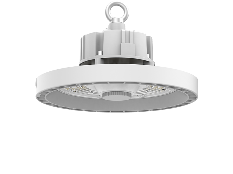
High bay light spacing between warehouse racks
Open-floor calculations often look good because every fixture contributes to every grid point. Tall racks interrupt that overlap. A layout may deliver 300 lux on the aisle floor while labels halfway up the rack remain difficult to read.
For racked warehouses, calculate vertical illuminance on the rack faces as well as horizontal illuminance on the aisle. Place rows over aisles, not over rack tops, and use an aisle or asymmetric distribution where appropriate. If rack positions may change, document the assumptions so that a future reconfiguration triggers a lighting review.
High bay light spacing near walls and corners
A symmetrical grid often leaves its first row half a normal spacing from the wall. That is a reasonable starting point in an open building because it allows the beam to meet the wall without placing a fixture directly against it. Doors, packing benches, perimeter racks and reflective wall panels can all change the requirement.
Review corners separately. A design can achieve a strong room average while the four corners fall well below the minimum. Adding one fixture to each corner is not always the answer; moving the end rows or choosing a distribution with better lateral coverage may use fewer units.
Coordinate high bay light spacing with the building
A photometric grid that ignores roof trusses, sprinklers, cranes and conveyors is not buildable. Before approval, overlay fixture positions with:
- roof purlins and permitted suspension points;
- sprinkler pipes and required clearances;
- crane rails and moving equipment;
- ducts, cable trays and skylights;
- racking and future expansion zones;
- emergency and maintenance access.
Moving a fixture one metre around an obstruction can be harmless or can open a dark strip through an aisle. Update the model after coordination instead of relying on the original concept layout.
Controls do not change high bay light spacing
Occupancy sensors and daylight dimming reduce energy use, but they do not allow a wider fixture grid. When every light is at full output, the installation must still meet the required maintained illuminance and uniformity. Controls change how long and how hard the fixtures run; optics determine where the light goes.
Zone sensors by activity. One sensor for a long aisle can leave workers walking into darkness while the far end wakes up slowly. Overlapping detection zones and a low standby level usually produce a safer result than switching alternate fixtures fully off.
How to verify high bay light spacing in the final calculation
- exact luminaire model, wattage and IES/LDT filename;
- fixture coordinates, mounting heights and aiming angles;
- calculation planes and work-plane heights;
- average, minimum and maximum maintained illuminance;
- uniformity and, where relevant, UGR;
- maintenance and utilisation assumptions;
- rack, wall and equipment geometry that affects the result;
- connected load and control zones.
Explore ROKEE’s LED high bay lights and linear high bay lights, then use the warehouse lighting design guide for the wider project brief. For a checked layout, send the floor plan, clear height, rack layout and target lux.
Frequently asked questions
How far apart should LED high bay lights be?
In many warehouses the preliminary spacing falls between roughly one and 1.3 times the fixture height above the work plane, but the exact value depends on distribution, output, target lux and room geometry. Confirm it with the product’s photometric file.
How many high bay lights do I need?
Use the lumen method for an initial quantity, then arrange the fixtures around aisles and structures and verify average lux, minimum lux and uniformity in lighting software.
Should high bay lights be centred over warehouse aisles?
Usually yes for tall racking, because the aim is to illuminate the aisle and rack faces rather than the rack tops. Open storage and production areas may use a regular structural grid instead.
Can I replace 400W metal halide fixtures one for one?
Only after checking the LED luminaire’s output and distribution. A one-for-one replacement may produce the correct average but poor uniformity or excessive brightness directly below each fixture.
Does wider spacing always save money?
No. A wider grid may require higher-output fixtures, increase glare and leave poor minimum light levels. Compare installed cost and energy after both layouts meet the same maintained-lighting criteria.
Authoritative references
Related Posts